HDMI, 10 & 14 pin camera connections
The HDMI Type A connector (13.9 mm × 4.45 mm male) is the most widely used, present on most TVs, recorders, and set top boxes.
The Mini-HDMI (Type C) connector (10.42 mm × 2.42 mm) is found on camcorders and DSLRs. The Type C pinout is similar to Type A but with positive signals swapped with their corresponding shield.
The Micro-HDMI (Type D) is intended for smartphones and similar small devices. It keeps the same 19 pins but in a much smaller package.
For historical reference, the 10-pin and 14-pin connectors from older video cameras are also included below (based on NATIONAL WVP-50N and SONY HVC3000C service manuals — pin-outs may vary by brand).
HDMI (Type A) pin connections
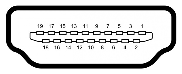
| Pin | Function |
|---|
| 1 | TMDS Data 2 + |
| 2 | TMDS Data 2 shield |
| 3 | TMDS Data 2 − |
| 4 | TMDS Data 1 + |
| 5 | TMDS Data 1 shield |
| 6 | TMDS Data 1 − |
| 7 | TMDS Data 0 + |
| 8 | TMDS Data 0 shield |
| 9 | TMDS Data 0 − |
| 10 | TMDS Clock + |
| 11 | TMDS Clock shield |
| 12 | TMDS Clock − |
| 13 | CEC |
| 14 | HEC Data− |
| 15 | SCL (serial clock for DDC) |
| 16 | SDA (serial data line for DDC) |
| 17 | DDC / CEC / HEC Ground |
| 18 | +5 V Power (50 mA max) |
| 19 | Hot Plug Detect (1.3) / HEC Data+ (1.4) |
Mini HDMI (Type C) pin connections
| Pin | Function |
|---|
| 1 | TMDS Data 2 shield+ |
| 2 | TMDS Data 2 + |
| 3 | TMDS Data 2 − |
| 4 | TMDS Data 1 shield |
| 5 | TMDS Data 1 + |
| 6 | TMDS Data 1 − |
| 7 | TMDS Data 0 shield |
| 8 | TMDS Data 0 + |
| 9 | TMDS Data 0 − |
| 10 | TMDS Clock shield |
| 11 | TMDS Clock + |
| 12 | TMDS Clock − |
| 13 | DDC / CEC Ground |
| 14 | CEC |
| 15 | SCL (DDC clock) |
| 16 | SDA (DDC data) |
| 17 | HEC + |
| 18 | +5 V Power |
| 19 | Hot Plug Detect / HEC − |
| Shell | Ground |
Micro HDMI (Type D) pin connections
| Pin | Function |
|---|
| 1 | Hot Plug Detect / HEAC − |
| 2 | Utility / HEAC+ (NC on device) |
| 3 | TMDS Data 2 + |
| 4 | TMDS Data 2 Shield |
| 5 | TMDS Data 2 − |
| 6 | TMDS Data 1 + |
| 7 | TMDS Data 1 Shield |
| 8 | TMDS Data 1 − |
| 9 | TMDS Data 0 + |
| 10 | TMDS Data 0 Shield |
| 11 | TMDS Data 0 − |
| 12 | TMDS Clock + |
| 13 | TMDS Clock Shield |
| 14 | TMDS Clock − |
| 15 | CEC (Control) |
| 16 | DDC / CEC / HEAC Ground |
| 17 | SCL (DDC clock) |
| 18 | SDA (DDC data) |
| 19 | +5 V Power |
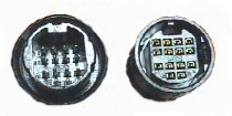
14 pin connector
| Pin | Function |
|---|
| 1 | Camera video out |
| 2 | Camera video ground |
| 3 | Viewfinder video in |
| 4 | Viewfinder video ground |
| 5 | Start/Stop |
| 6 | Tally signal in |
| 7 | Camera audio out (CH2) |
| 8 | Record/Review button |
| 9 | Camera audio out (CH1) |
| 10 | Audio ground |
| 11 | Audio in (CH1) |
| 12 | Audio in (CH2) |
| 13 | +12V DC in |
| 14 | Ground |
10 pin connector
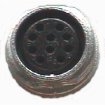
| Pin | Function |
|---|
| 1 | Camera video out |
| 2 | Camera video ground |
| 3 | Viewfinder video in |
| 4 | Viewfinder video ground |
| 5 | NC |
| 6 | Record/Pause out |
| 7 | Camera audio out |
| 8 | Camera audio ground |
| 9 | DC ground |
| 10 | +12V DC in |
