
1.2 GHz (23 cm) 20 W RF amplifier
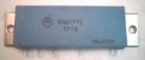
With modified Motorola MHW1915 / MHW1918 hybrid module
Original modification by IK8UIF, English translation by VK3GE
Block diagram and practical application circuit
The modification
First remove the module from its original circuit. The module's blue cover is glued at each corner — use a screwdriver under a corner with some leverage to pop the case off. Beware: there are tiny components inside that are easily destroyed. The transistors are unprotected once the cover is removed.
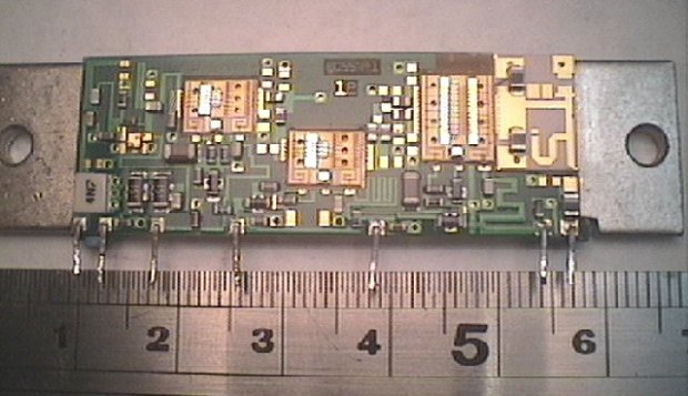
Module interior with cover removed
Step 1
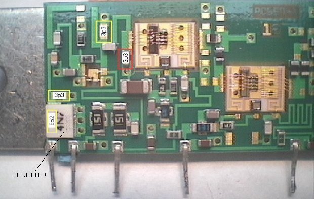
Remove the input capacitor marked 4N7.
Step 2
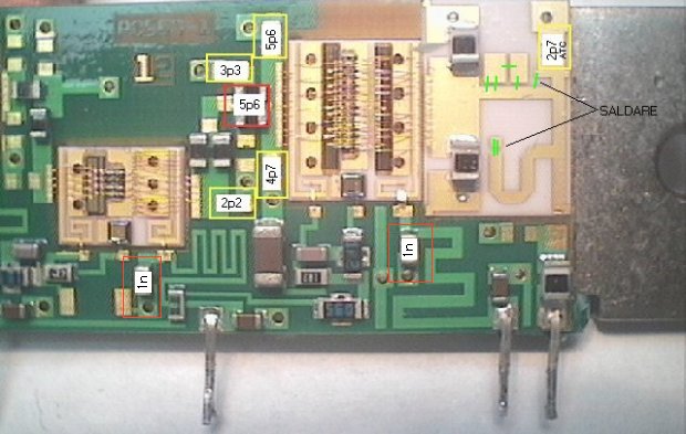
Place chip capacitors on empty pads as shown in yellow boxes in the photos below.
Step 3
Place chip capacitors shown in red boxes in parallel with existing components.
Step 4
The capacitor marked 2p7 in the yellow box on the right side should be an ATC type due to high internal temperatures.
Step 5
The green lines in the photos show points on the output strip line that must be connected.
Step 6
Replace the blue cover and secure with a small amount of glue on the edge.
Step 7
Once modifications are complete the module is ready for use.
Module interior — left side
Module interior — right side
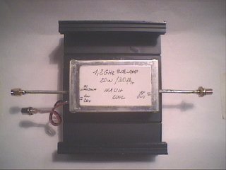
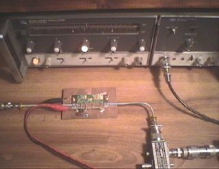
Practical implementation
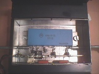
Bolt the module into a metal box with heat transfer compound to maximise heat transfer. The box needs an external heat sink. In the author's implementation, input and output are fed by UT141 semi-rigid coax with SMA connectors. A 5 V regulator (7805 or similar) supplies the bias voltage to pin 4. Pins 2, 3, 4, 5, 6 should have a ferrite bead on each leg next to the module. The power supply should enter via a feed-through capacitor with liberal use of 1 nF ceramic or chip capacitors on the supply line near the module.
Testing
Use a 13.8 V supply initially. Apply approximately 10 dBm (10 mW) input and a maximum of 17 dBm (50 mW) at 1240 MHz. Output should be 5–7 W. A supply of up to 24 V can be used to increase output to approximately 15–20 W.
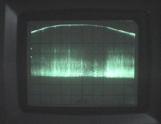
Test results from the author (module fed at 13.8 V):
 |
 |
| Fstart = 1190 MHz, Fstop = 1290 MHz, FC = 1240 MHz Ref level = +40 dBm (10 W) Display: 10 dB/div vert, 10 MHz/div horiz BW−3dB ≈ 60 MHz at Fc = 1240 MHz |
Setup: HP8620A + 8622 sweep generator (0.01–2.4 GHz) HP141T + 855 + 8552B spectrum analyser EME precision directional coupler (−20 dB at 1.2 GHz) 50 W dummy load |
The amplifier can be used across the entire 23 cm band. 73s de IK8UIF Alberto